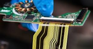
Uniformity in Rigid Flex PCB Manufacturing
Rigid flex circuits combine both rigid and flexible substrates, adding strength and dynamic adaptability to the overall board. The flex substrates are used to carry components and provide interconnection paths, while the rigid sections are used for structural support. While rigid-flex PCBs offer many advantages, they also come with a unique set of manufacturing and assembly challenges.
Several factors can cause rigid flex circuits to delaminate or fail, including improper adhesive selection and inadequate thermal management. Additionally, the complexities of rigid-flex circuit manufacturing can lead to mistakes that may impact the final product’s performance and reliability. Using rigid-flex circuits requires special care in the design process to ensure uniformity across multiple processes and to minimize DFM mistakes that can reduce yields and cost.
One of the most common DFM mistakes is poor hole-to-flex spacing. This can lead to mechanical stress concentration, tracing thinning, signal integrity concerns, and solder joint reliability issues. To avoid these problems, it is important to use a large plating thickness on the flex layer, avoid overlapping copper areas on the flex layer, and stagger traces near bend regions.

How to Ensure Uniformity in Rigid Flex PCB Manufacturing
Another important DFM mistake is omitting adequate stiffeners in the flex section of the board. This can cause premature failure of the flex circuits due to excessive bending. Stiffeners should be placed every 6 to 12 inches along the length of the flex section to prevent premature bending and to keep the flex circuits in a straight, unbent position during reflow soldering.
Adequate flex-to-rigid transition area clearance is also critical to rigid-flex design and manufacturing. This clearance is necessary to protect the conductor paths from mechanical stress and inadvertent damage during assembly. This clearance should be at least 10 mil, but should be as large as possible to minimize the risk of failure.
Additionally, the flex-to-rigid transition region should be plated with copper and covered with a protective material to prevent delamination from adhesive squeeze out or protrusion of dielectric materials. Lastly, the flex-to-rigid area should be free of sharp angles to avoid stress concentration in the flex circuit and prevent damage during bending.
With these DFM mistakes in mind, it is crucial to consult a qualified designer who understands rigid-flex PCB design and manufacturing. A professional PCB manufacturer will be able to provide the right solutions for your design, and they can ensure uniformity during the rigid-flex fabrication process. Contact us today to learn more about our expertise in rigid-flex PCBs and the services we offer, or try our online PCB design software for yourself with a free trial of Altium Designer + Altium 365. You can create and submit your design for production in just a click!